
The controller calls.
A program sends a low-voltage command to one station. A rain sensor or weather adjustment may prevent the cycle.
THE GARDEN SAGE / HOMEOWNER LEARNING SERIES
Understand the whole system. See how every part works.
Start with the whole system. Follow the water.
Then explore each part and see how it works.
01 / THE COMPLETE SYSTEM
Start here: follow the blue water path.
Select a part or the R rain-sensor marker to explore it below.

Zone 1 is watering. The other zone valves are closed.
The rain sensor is exposed to natural rainfall. Wet/dry is a teaching test; a real sensor takes time to dry. This example shows automatic watering with the sensor enabled.
Two meters share the public supply. Irrigation water passes through its own meter without passing through the house meter.
Illustrative layout. Pipe depths, lengths, component sizes and spacing are not to scale. Backflow type, regulator position and component order depend on the approved design. Some systems also have a master valve. This guide does not operate your actual irrigation.
A program sends a low-voltage command to one station. A rain sensor or weather adjustment may prevent the cycle.
The solenoid changes pressure inside the valve. The diaphragm lifts, opening that zone to the water supply.
Pressure raises the sprinkler stems. Their nozzles distribute water while the other zones remain closed.
The command ends and the valve closes. The next station runs, or the controller returns to standby.
02 / THE COMPONENT LAB
Seven working models. Three ways to see them.
Recognize the part as it appears in a real system.
03 / PROTECT
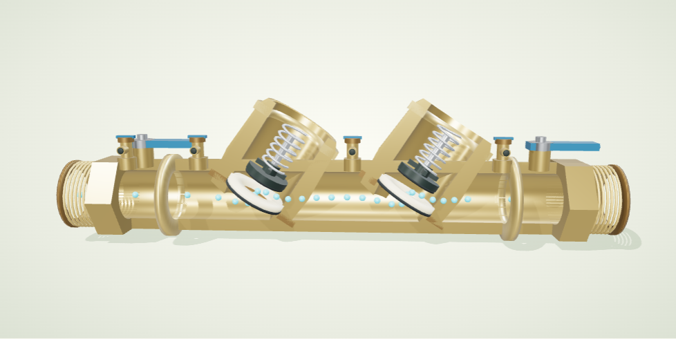
Two independent checks help prevent irrigation water from returning toward the drinking-water supply.
Practice programming this type of controller ↓CHANGE THE CONDITIONS
Water pressure opens both checks toward the irrigation side.
AUTOMATIC WATERING · RAIN SENSOR TEST
A wet sensor pauses automatic watering. Select dry to restore the demonstration; real sensors need time to dry.
Choose Cutaway to see the internal mechanism.


Representative teaching models, built to explain the mechanism. Exterior details and internal geometry vary by manufacturer; these are not exact manufacturer CAD, installation drawings, or hydraulic simulations. Blue particles indicate flow direction.
The supply powers the controller. Its two low-voltage leads enter dedicated input terminals.
One lead from every valve joins the common wire. Follow its continuous branch back to C.
Each numbered terminal controls a separate coil. Select Station 1, Station 2 or Off to compare.
A normally closed contact opens when wet. The controller stops automatic station outputs while keeping its power supply on.
Colors identify functions in this teaching model. Actual wire colors vary; identify connections by their terminal markings. The closeup shows two stations; the property map has three. Each additional conventional zone needs its own station wire and a connection to common.
The standard connections shown are power, common, individual station wires and the wired rain-sensor pair. The two SEN terminals are not bridged by a jumper when this sensor is connected.
Use the manual for the exact controller. Sensor bypass settings and some manual-watering functions can override a wet sensor.
UNDERSTAND THE MECHANISM
03 / TRY THE CONTROLLER
Learn the everyday settings before you open your own control box.
A practice controller inspired by common Hunter and Rain Bird dial layouts. It teaches shared programming concepts, rather than copying a particular model’s buttons or firmware. Example days and durations are for learning, not a watering recommendation. Nothing here controls your irrigation.
| Program | Start slots 1 · 2 · 3 · 4 | Zones 1 / 2 / 3 | Watering days |
|---|
This simplified lesson uses a fixed practice clock, weekday scheduling, and 100% seasonal adjustment. The separate 3D rain-sensor test demonstrates automatic inhibition; this programming exercise does not simulate weather. Seasonal changes, calendar cycles, Wi-Fi control, manual starts and overlapping-program queues vary by model and are outside this lesson. OFF stops automatic commands but does not shut off the water supply. Practice settings reset when you reload.
04 / WHY A SECOND METER?
A sink sends water to a drain.
Your sprinklers send it into the landscape.
A dedicated meter makes outdoor use visible. Where your utility allows it, that measurement can keep eligible irrigation water out of the volume used to calculate sewer charges. You still pay for the water.
Installation, service fees, water rates and backflow testing affect the total cost. A second meter does not automatically guarantee savings or a sewer credit.
A meter measures volume. Water-supply pressure and the system’s hydraulic design determine how much flow is available.
Each meter records only its own branch. The irrigation service can have its own account and billing treatment. The branches split before the meters or use separate utility taps.
The main meter counts everything first. The submeter measures the irrigation portion already included in that total. Any sewer deduction needs the provider’s approval and reporting process.
A SUBMETER EXAMPLE · VOLUME, NOT A BILL ESTIMATE
Do not add the submeter reading to the main reading. The garden’s water has already passed through the main meter.
05 / KNOW YOUR OWN SYSTEM
You do not need to dismantle anything to understand your irrigation. Start with a simple map of your property.
Ask The Garden Sage for help ↗Identify the accessible valve that isolates irrigation. The controller’s OFF setting does not remove supply pressure. Leave utility-owned valves and seals alone.
Match the serial number to your bill. Confirm whether it is a separate service or an approved submeter, and check the reading units.
Record the model and testing information. Your provider determines the approved protection and testing requirements. Never bypass the assembly.
Label each station with the area it waters. Mark the valve boxes on your map and keep their lids accessible.
WHEN SOMETHING DOES NOT SEEM RIGHT
Supply pipes can stay pressurized even when stations are off. Continued movement on a dedicated irrigation meter after the system settles can indicate a leak, a valve passing water, or another connection. A house main meter can also move because water is being used indoors.
A valve may be obstructed, damaged, or held open manually. Removing its electrical signal cannot close a mechanically stuck valve. If needed, close the identified customer irrigation shutoff and arrange service. Do not open a pressurized valve or backflow assembly.
A reducer limits excessive pressure; it cannot create pressure or water volume. Weak coverage may involve a leak, restriction, oversized zone, inadequate supply or incorrect nozzle. Pressure measured while water is flowing can differ from static pressure.
No. The supplied Wilkins 950XLT reference is a double-check assembly for low-hazard protection. The approved backflow type depends on the utility and hazard. A reduced-pressure assembly has a relief zone, and vacuum breakers have different operating and installation requirements.
No. Water remains in many pipes and components. Seasonal shutdown and winterization need to match the actual installation and local conditions. Arrange system-specific service.
THE SOURCES BEHIND THE MODELS
Manufacturer literature and utility guidance inform these explanations. Use the documentation for your installed model and your provider’s requirements for service decisions.